mechanical systems
Bumpers
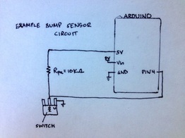 Single bump switch circuit
Four bumpers were placed on the robot and named left front, right front, left back, and right back. They were laser cut out of duron and toleranced by nuts on the axial threaded rod that provided structure for our robot layers. When the duron was depressed, it hit the switch and closed the circuit, turning the bumpers to 'ON' - or a state of 0.
Testing showed that the relatively thin duron was not consistently the same height as the obstacles the bot needed to hit. To solve this additional foamcore walls were added to the bumpers such that they would be depressed at the low height of the wall (to react in case we were off target and ran into the stadium walls) and also would be depressed at the exchange (such that we could use both front bumpers to align our bot before going through the button press sequence to obtain BitCoins).
Testing also showed that only gluing the bumper switches to the duron was not secure enough, the force of getting bumped several times would shear the switch from the glue so we needed to also add screws for a more reliable bumper.
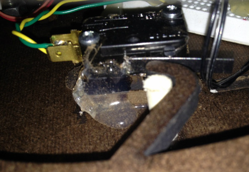
Installed bump switch, with duron mounting, glue and screws
RAMP
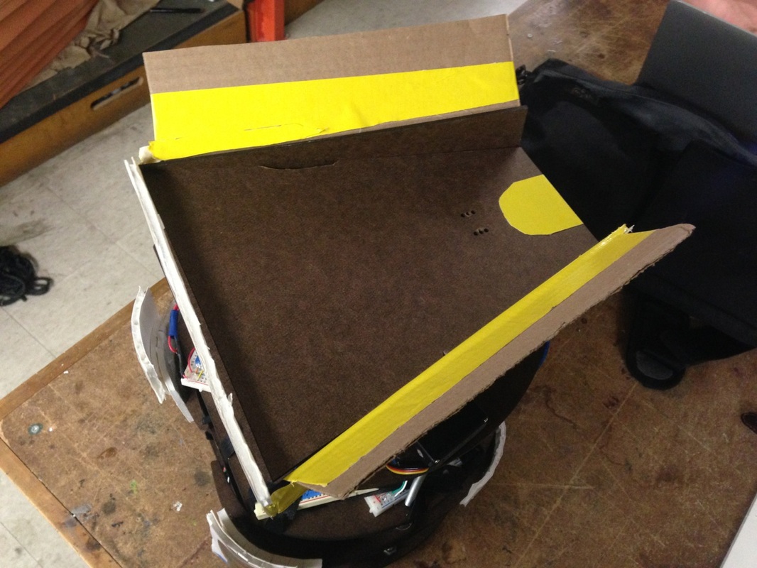
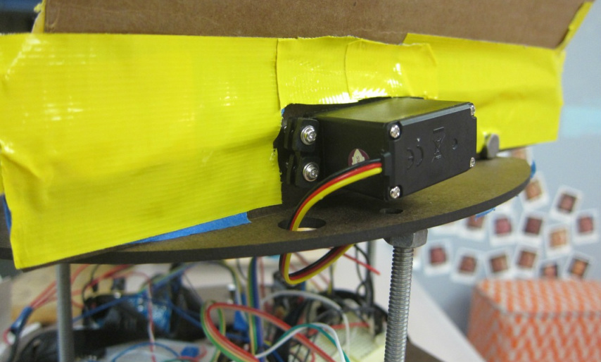
In order to deposit the BitCoins into the Exchanges, we designed and constructed a hinged ramp that was actuated by a servo motor. When the bot went into 'search for exchange' mode, it used the IR sensors to move forward towards the middle exchange. It would usually hit with one front bumper, and adjust itself to be dead on with the exchange, therefore depressing both front bumpers. When both front bumpers were depressed, the servo would actuate, raise the ramp, and dump the coins.
After the checkoff, we realized that sometimes the ramp would not actuate if the alignment was off such that the ramp was over a corner of the exchange. If this happened, the ramp could not drop enough to release the coins. In order to fix this, we moved the hinge from the center of the ramp to the very bottom front of the ramp, and lengthened the servo arm. This allowed the ramp to actuate even over a corner of an exchange, with an arm long enough to push the ramp high enough to ensure all the coins would be dropped.
After the checkoff, we realized that sometimes the ramp would not actuate if the alignment was off such that the ramp was over a corner of the exchange. If this happened, the ramp could not drop enough to release the coins. In order to fix this, we moved the hinge from the center of the ramp to the very bottom front of the ramp, and lengthened the servo arm. This allowed the ramp to actuate even over a corner of an exchange, with an arm long enough to push the ramp high enough to ensure all the coins would be dropped.
MOTORS
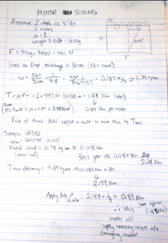
We performed initial motor sizing calculations to confirm if the Jameco 161382 would provide sufficient torque.
Assumptions:
- 10lb bot
- 2 motors
- 2 wheels of 3in diameter
- based the speed on the bot traveling from the server to one of the far exchanges in 30 seconds
Our calculations determined that each of our motors would need to provide 0.84 Nm, and the 161382 motors provide over 2 Nm, so these motors would be sufficient. However there is a rule of thumb that a motor should not be subjected to greater than 1/3 Tstall, so these motors were just on the edge of being acceptable, and in testing our bot was difficult to control and behaving unpredictably. We discussed our problem with Matt and he suggested motors with higher torque. So we traded our motors out to the Jameco 155855, which are the same motors as the 161382 but with a 60:1 gear ratio, instead of 30:1. This change provided much more control and minimized the bot sliding along the floor, especially when stopping and turning.
We initially planned to use the LM293 for the motor driver circuit, but our motors did not operate correctly and we determined that the 1A maximum for this circuit was too low for our motors to start so we switched to the LM298, which has a 2A maximum.
POWER CIRCUIT
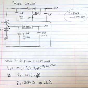
We were provided two 8.4V batteries, but needed a 12V voltage source for our motors and Arduino, and a 5V voltage source for our logical circuits. We designed a power circuit using two voltage regulators to provide these two outputs.
The LM7805C is designed to provide a 5V output, but the LM317 is a variable voltage regulator so we needed to size the correct resistor for the circuit to result in 12V. Based on the data sheet we calculated that we needed 2kOhms.
We added a red LED to the circuit so that we could easily see whether the power circuit was on and functioning, on and malfunctioning, or off. Initially the LM317 was getting very hot so we added a heat sink to that regulator and had much better performance afterwards.
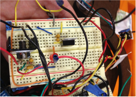
Photograph of the circuit breadboard
